NanoGuide - reading sample
Nanoscribes extensive online knowledge base NanoGuide provides detailed information and guides on Nanoscribe hardware, software, photoresins and print processes. As a Nanoscribe user, NanoGuide is your 24/7 support portal with the latest information on 3D Microfabrication. Below, you can read an article about CAD model creation as a reading sample to get a first impression of NanoGuide. Please note that the underlined words are actually links within NanoGuide, which have been disabled for the sake of this sample. Enjoy reading!
_____________________________________
NanoGuide article:
CAD Model Creation
The 3D printer uses a proprietary General Writing Language (GWL) file format to print structures. The companion software DeScribe prepares GWL files and also handles import and modification of Standard Tessellation Language (STL) files exported from CAD applications. Once the import is complete, the compiled files are loaded into NanoWrite for printing.
The STL file format defines the closed-surface geometry of a 3D solid object. Upon exporting to STL, the model surface is approximated by a set of tessellated triangles (Figure 1). Although most CAD applications offer STL file export, there is significant variation in the quality of the surface model generated. A good model without holes or self-intersections is essential for further processing. Always choose a reasonable accuracy setting when converting into STL.

The following commercial CAD applications are capable of generating STL output of sufficient quality:
- AutoCAD
- Autodesk Inventor
- PTC Creo
- SolidWorks
STL files can be created with Tinkercad (Autodesk), which is freely available for download. STL files of varying quality can be downloaded from the internet (e.g. Thingiverse). Some common defects in STL files can be fixed with the open-source program Meshlab or the built-in mesh repair function within DeScribe itself.
Issues commonly encountered during STL import
Watertight models
Ensure that the model surface is completely closed without gaps or voids. If these are present (Figure 2-1), DeScribe attempts to repair the surface during import, however, the software must approximate the surface shape. In this case surface modifications that differ from the intended shape could manifest (Figure 2-2).
Figure 2: Non-watertight surfaces must be repaired, which may lead to unexpected results.
Other programs like NetFabb offer advanced mesh repair options.
Surface tessellation during STL export
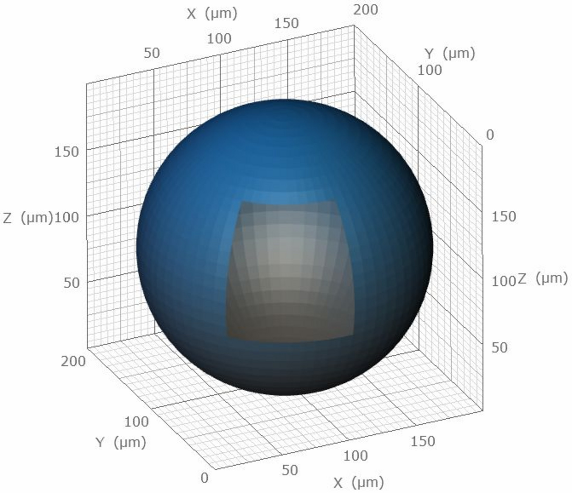
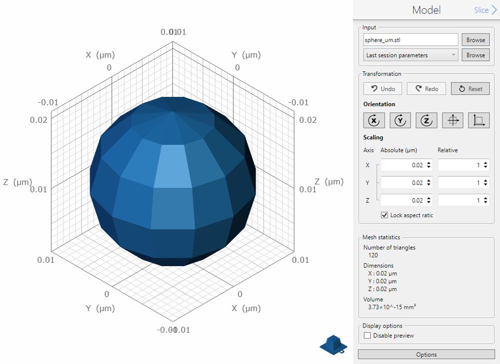
The STL file format is dimensionless, in the sense that CAD dimensions of 20 mm are exported as 20 units. DeScribe interprets any unit as micrometer. Thus 20 mm of the CAD model will be displayed as 20 μm in DeScribe. If an external CAD program is set up to display millimeters but the model is designed in micrometers (e.g., 0.02 mm; Figure 3), the resulting model may appear too small in DeScribe (0.02 μm; Figure 4).
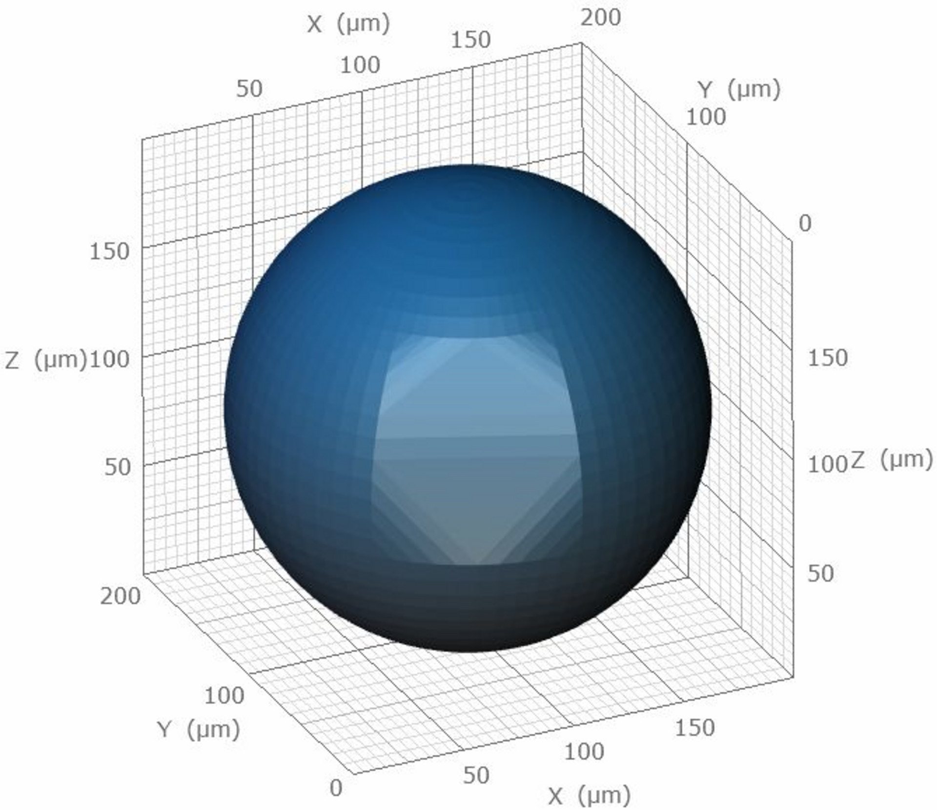
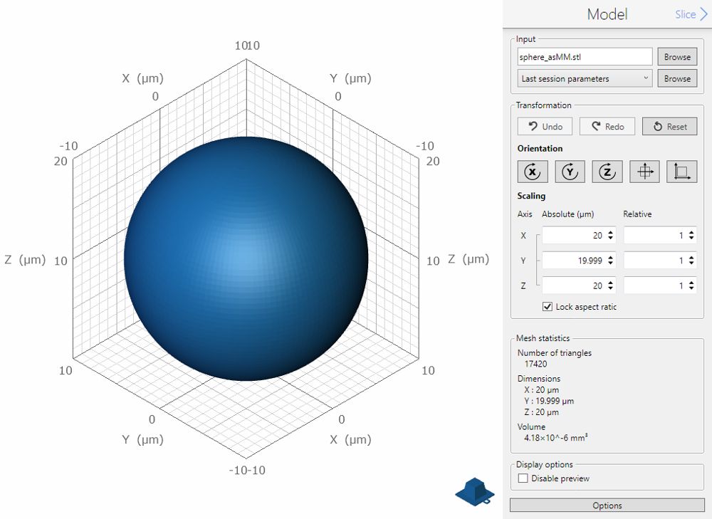
Depending on the export capability of the CAD program, the surface mesh could be very coarse (Figure 3,4), resulting in poor printing quality. This coarseness might result from the unit scale the model was created with. As the model in Figure 3 was created using the millimeter scale, the CAD program failed to export the STL data with a sufficient number of triangles. The model in Figure 5 was designed in the micrometer scale and more triangles were used during export. Thus, the resulting sphere is smoother.

Accuracy setting during STL export
The maximum accuracy setting during STL export may generate very large file sizes, which could lead to issues when importing the STL file into DeScribe. Insufficient accuracy leads to surface roughness in the worst case, as elaborated above. Choose a reasonable accuracy setting and a appropriate PC for the import.
Self-intersections
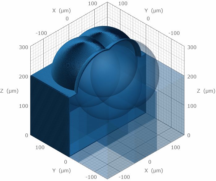
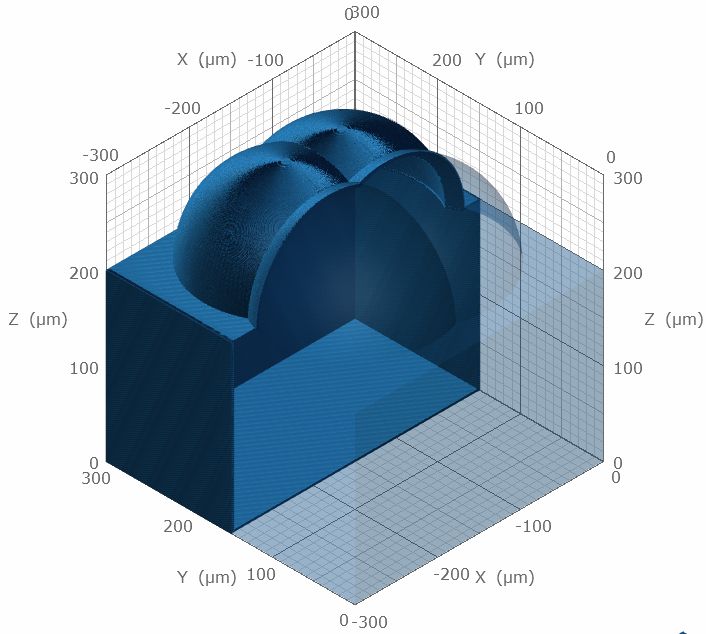
When creating a structure out of multiple self-intersecting bodies (Figure 6-1), merge all sub-parts before STL export to create one whole structure (Figure 6-2). If DeScribe encounters multiple sub-structures during import, unexpected slicing and hatching may occur. DeScribe will attempt to repair self-intersections; for instance the example structure in Figure 6-1 is correctly treated as one single merged body and is identical to Figure 6-2 after import, as a result of the import algorithm of DeScribe.
Figure 6: Structures imported into DeScribe with (6-1) and without (6-2) self-intersecting bodies.